Drawing Machine
This page includes the documentation of creating a machine by fab lab Bahrain Students:
- abdalgfor ismail
- Maryam Ali
- Hawra Al Rahma
- Abdukajalil Alkoheji
Assignment
Work and communicate effectively in a team and independently to make a machine, including the end effector, build the passive parts and operate it manually. And automate and document the work.
Project Concept
Our group project is a hanging drawing machine that moves its hand in two axes (X, Y). The hand conists of a pen attached to a 3D printed holder that connected to two stepper motors from the right and left sides. The machine should be attached vertically to a board and being controlled by a g-code.
The aim of this machine is to enable the user to draw anything on a board or a wall. Requirements are simple as the user should just fix the machine on the panel want to draw on and enter the size of the drawing area and machine specifications.
Individual Contributions
| No. | Student name | Task |
|---|---|---|
| 1 | Abdalgfor Ismail | Stepper motor test + mechanical setup and installation for the board |
| 2 | Maryam Ali | Programming + debugging |
| 3 | Hawra Al Rahma | Writing Future development opportunities + create an image with inkscape for testing + Final machine video |
| 4 | Abdukajalil Alkoheji | 3D designing and printing |
BOM
All materials and devices used to build this machine are listed in the table below:
| Qty | Component name |
|---|---|
| 1 | Whiteboard |
| 1 | Whiteboard marker |
| 1 | Toothed belt |
| 1 | Arduino UNO |
| 1 | Power adaptor |
| 1 | Servo motor |
| 2 | Stepper motor |
| 1 | CNC shield |
| 2 | MP6500 Stepper motor driver |
| 2 | Heatsink for the stepper motor driver |
| 1 | Power supply |
| 1 | Digital multimeter |
| 1 | Screwdriver |
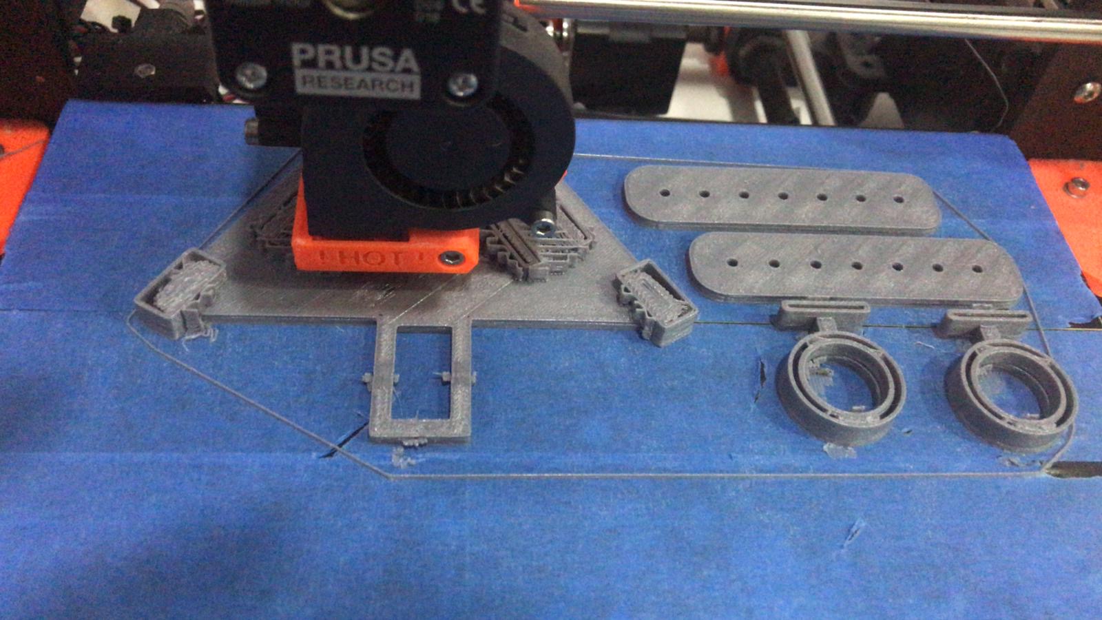
Design
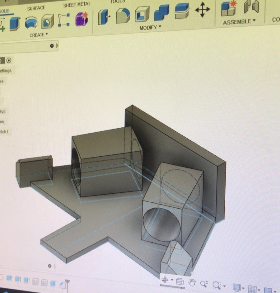
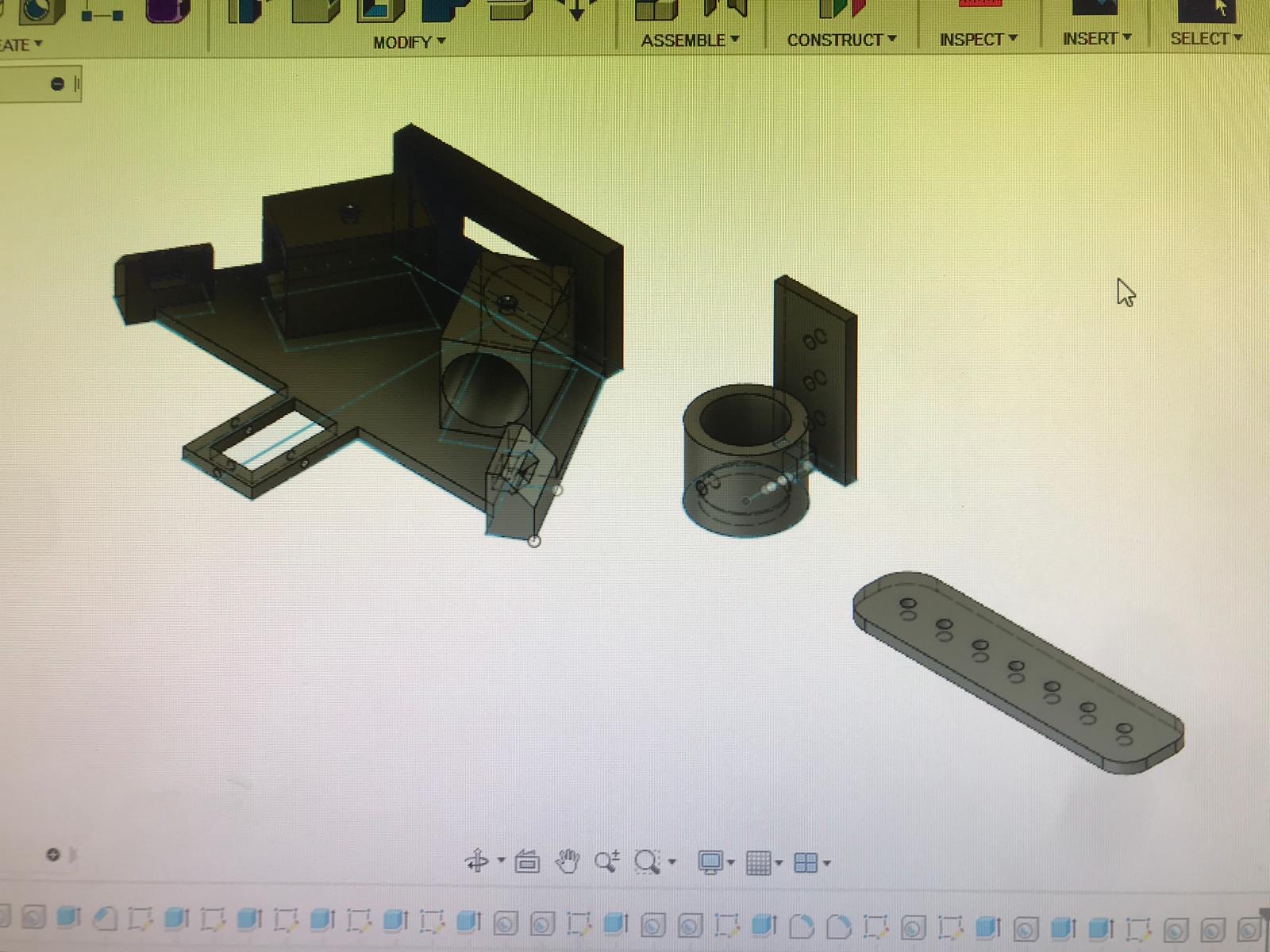

Structure and Building

Electronics
Polograph
My first try programming was using Polograph as explained in this tutorial. Software requirements for this tutorial includes installing Arduino IDE and Processing IDE.
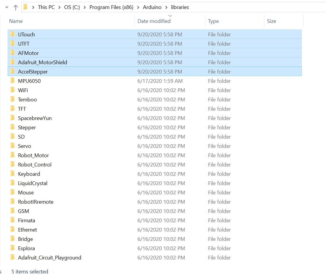
First, I downloaded polograph libraries files from here. I copied the arduino libraries from ((..\arduino-source\libraries)) folder and added them to Arduino IDE libraries.
Then I opened the source code ((Polargraph\arduino-source\polargraph_server_a1)) and uploaded it to Arduino UNO.
Then I openend polograph Contorller file on processing IDE from ((Polargraph 2017-11-01\controller\application.windows64\polargraphcontroller)), but I got an error message about (size) function.
So I made a research about it and found some people that got same error as mine and they solved it by installing an older version of processing IDE. So I did what they recommend and installed Processing IDE version 1.5.1 for windows from here. Finally, my g-code is uploaded !
polograph from Maryam Ali on Vimeo.
Then I started navigating the User interface and changed the machine settings from the SETUP tab based on the hardware that we are intended to use.
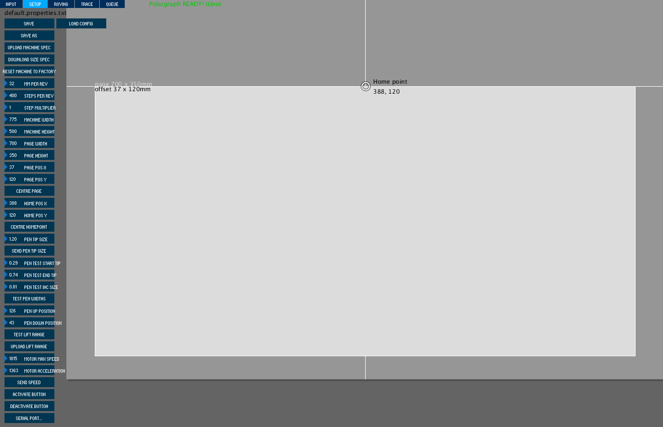
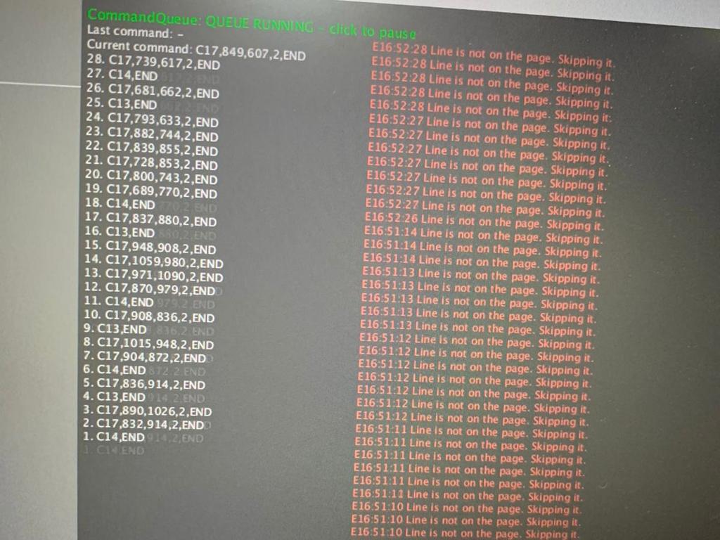
I uploaded a vector file, the g-code seemd uploaded correctly, but I got an error which said that "line is not on the page, skipping it." we tried to connect one of the stepper motors, but it won't run. So, we decided to shift to another software to save time.
Universal G-Code Sender
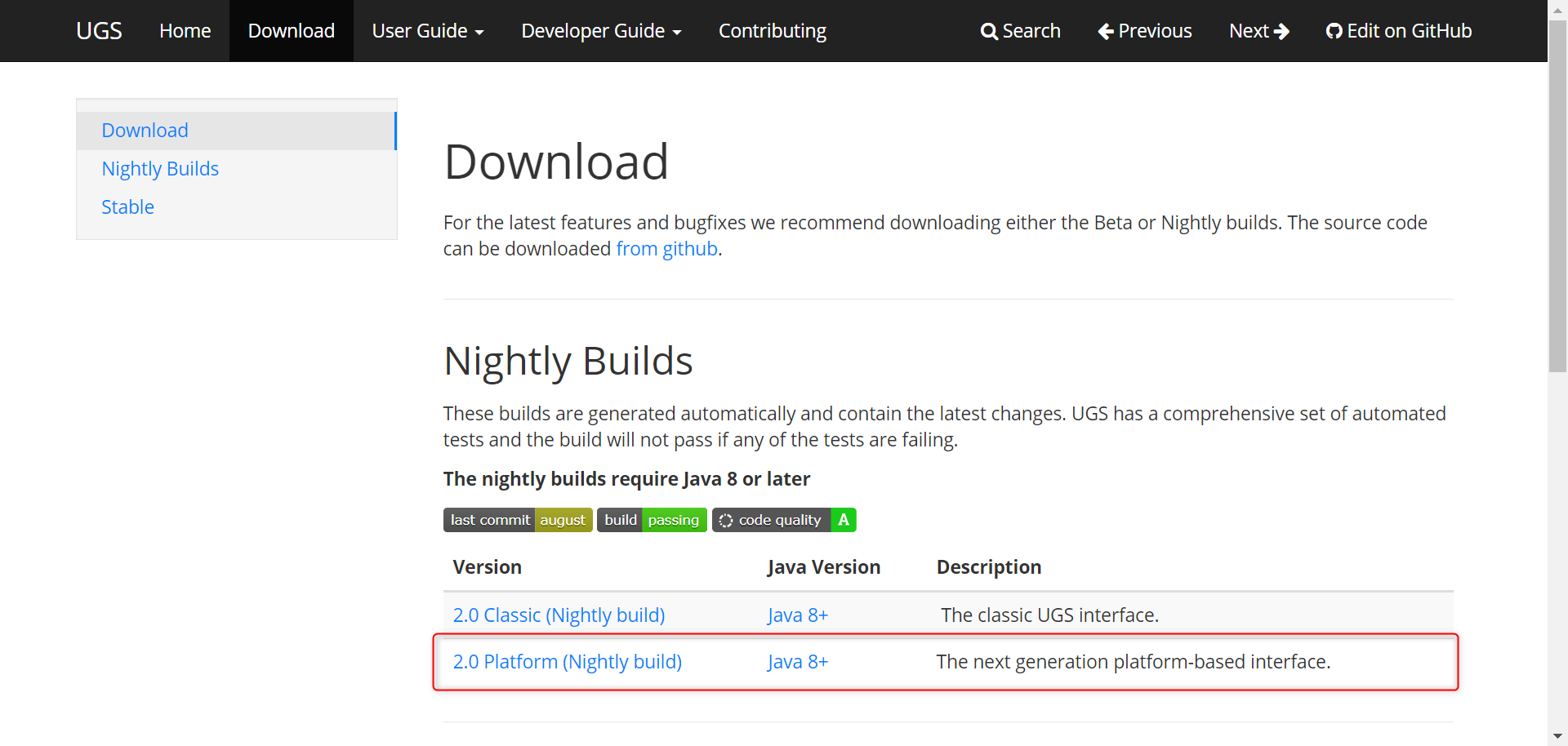
I decided to try Universal G-Code Sender. First, I have downloaded it from here. Howerver, I didn't know how to install it from the previous mentioned link, so I followed this tutorial. Another downloading link is mentioned in the tutorial, which is this one. So I have deleted the previous one and used the new one.

Universal G-Code Sender is a java based firmware, so first you need to install java from here if you don't have it on the PC you are using.
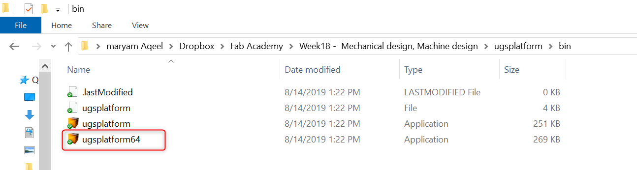
When the ugsplatform folder is downloaded, open the bin folder and run the application that suit your PC; for me I run ugsplatform64.
Main page of Universal G-Code Platform:
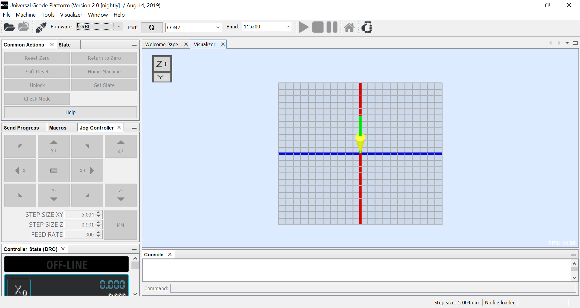
First test:
First, I have tried moving one stepper motor manually using X and Y arrows and it worked. Test process is shown in the following video.
Universal G-Code Sender Test from Maryam Ali on Vimeo.
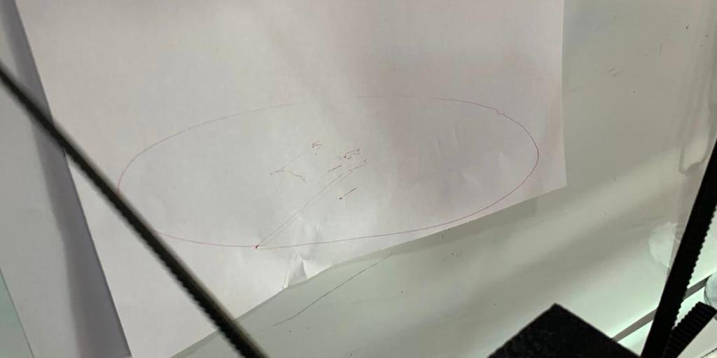
Second test:
After that, I sent a simple g-code, which is a circle. You can download it from here. As shown in the following video, we were using a big pen holder that designed by on of my group members to hold two pens and shift between the pens using a servo motor in the front middle. The result was unstable movement of the pen and unclear shape was drawn.
Circle Test from Maryam Ali on Vimeo.
The result:
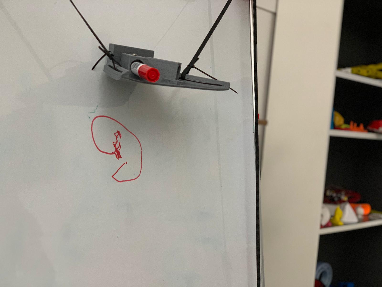
Third test:
Later, we decided to use a smaller design for the pen holder and send the circle g-code again. The result was a more stable movement of the pen, however the circle was drawn as an oval shape.
Circle Test 2 from Maryam Ali on Vimeo.
Final result:
Grbl Controller
Later, I have searched about other alternative softwares to send the g-code and found this useful tutorial that uses Grbl Controller.
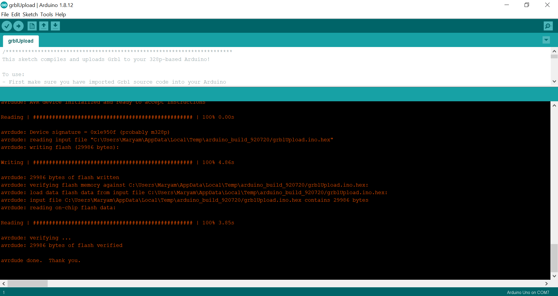
First step is to download Grbl from here. Then copy the grbl-polar-master folder and paste it in the Arduino IDE libraries folder in your PC. After adding the Grbl library, open grblUpload example code and upload it to your microcontroller ((Arduino UNO)).
I got the following error when I uploaded the code to Arduino UNO first time.
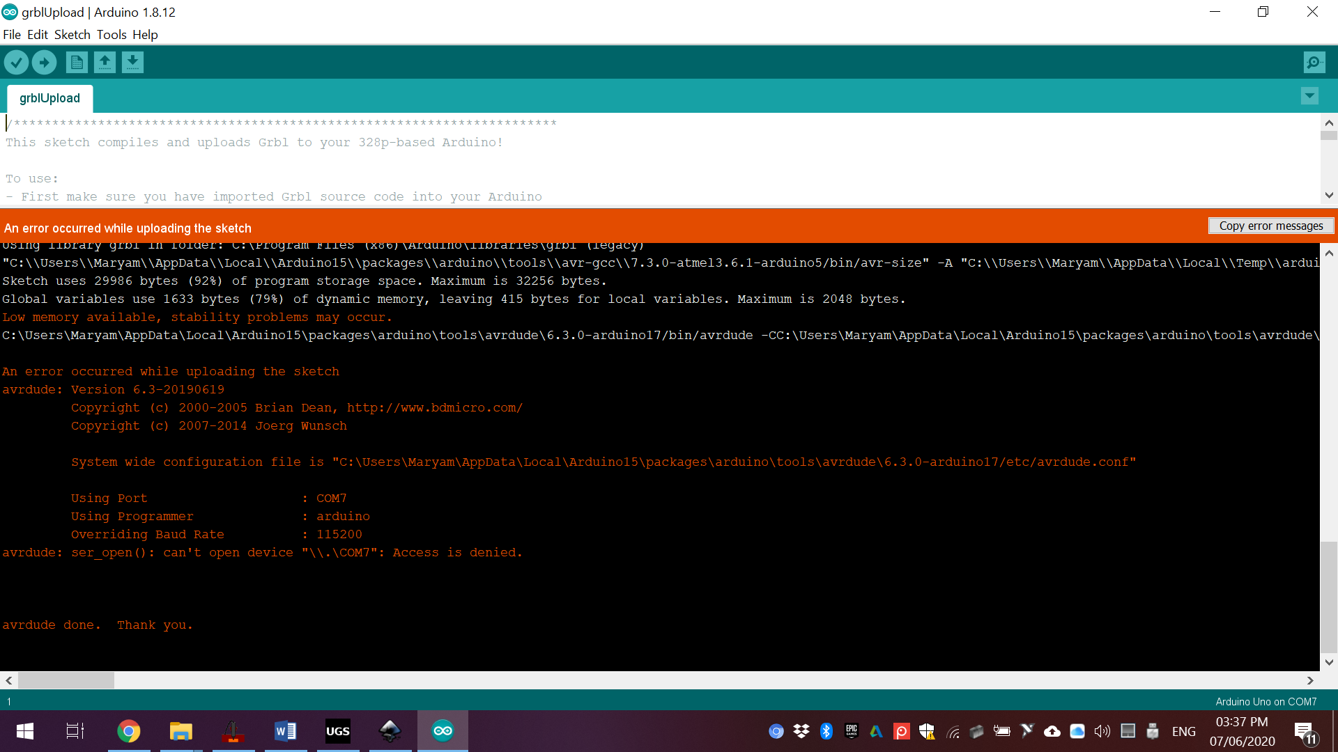
After disconnecting and reconnecting Arduino UNO USB, the code was uploaded but servo motor still not moving. Even though, we have moved to the next step because the time is running out.
Next step is to open Grbl Controller, select the correct port name of your Arduino UNO, Baud Rate, choose the file you want to send and click Begin. However, the result was the same when uploading the circle g-code, which is an oval shape drawing.
Current limiting:
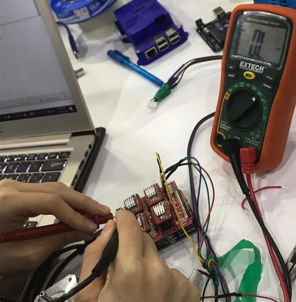
We found that we should set the current limit on the stepper motor driver using the VREF voltage before connecting it to the stepper motor. To do this, we used a power supply, a digital multimeter, a small screwdriver, and of course our stepper motor driver system connected to the CNC sheild. We have followed the tutorial video in Pololu site.
First, you need to determine the amount of cuurent you want to use to run the stepper motor so you should start with finding the rated current per phase of the motor (i.e. maximum current that the motor was designed for). It is written that the current limit = 1.5 A on the stepper motors we are using. Then you can use this value in the current limiting equation to find the VREF that you need to set:
Current Limit = VREF*2
1.5 A = X*2
X = 0.75 V = 750mV
Next, connect the power supply to the CNC sheild and set the power to 5 Volts. Use the digital multimeter to measure the voltgae at the VREF. Use a acrewdriver to screw or unsrew the potentiometer in order to change the VREF value.
Problem faced:
We found that there is a missing jumper wire on the CNC sheild under the motor driver place. That might be the reason for the unbalanced movement between the two stepper motors.

Grbl running:
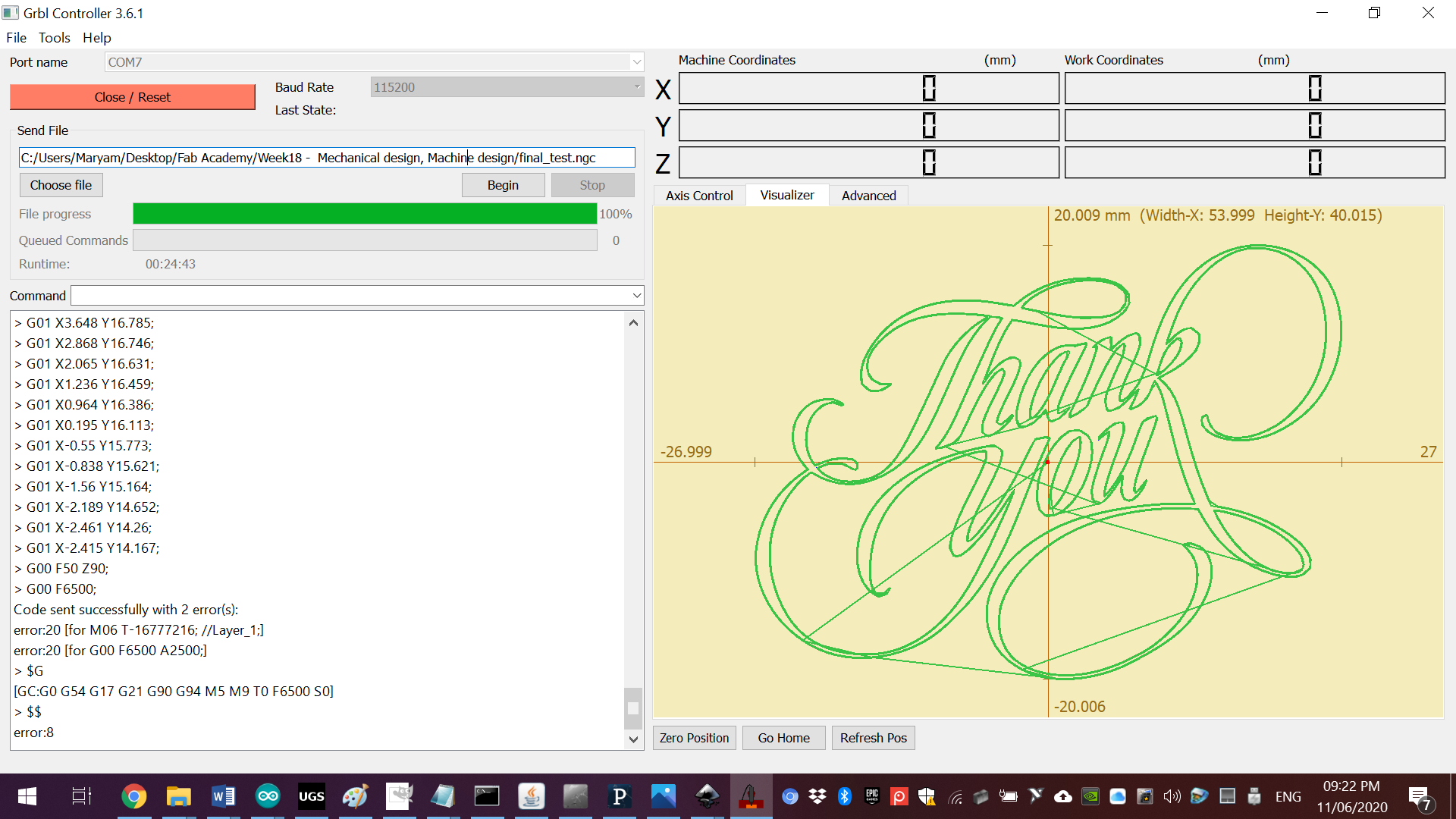
In the Grbl Controller, I have selected the correct port name of my Arduino UNO (COM7), Baud Rate (115200), chose the circle g-code again and click on Begin.
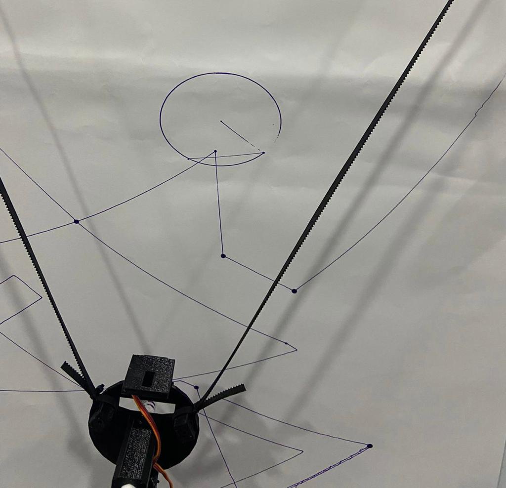
Finally, the circle shape is drawn accurately. So we tried to send another file, which is this file and click on Begin.
Final result: