Input Devices
Group Assignment
For this week group assignment we have to probe an analog and digital input devices. For that we used ultrasonic sensor to monitor the digital signal, and temperature sensor to measure the analog signals.
The Different between Analog and Digital Signals
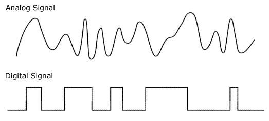
Analog input signals can represent temperature or level or flowrate, because analog signals are variable which have multiple states. It is a continuous signal that changes over a time period. The sine waveform represents analog signal.
Digital signal is a discrete signal that carries information in binary form. Digital input signals are used to represent items that only have two states, such as ON and OFF states. The square waveform represents the digital signal.
Monitoring digital Signal Using HC-SR04 Ultrasonic Sensor
Ultrasonic sensors are integrated with an Analog-to-Digital (ADC) converter. Ultrasonic sensors used to measure the distance from 2cm to 400 by sending a sound pulse, above the range of human hearing (ultrasonic), toward the target and then measuring the time it takes the sound echo to return. Knowing the speed of sound, the sensor determines the distance of the target and sets its outputs accordingly.

We will read the distance twice once on the Arduino Serial Monitor, and again with the Osciliscope.
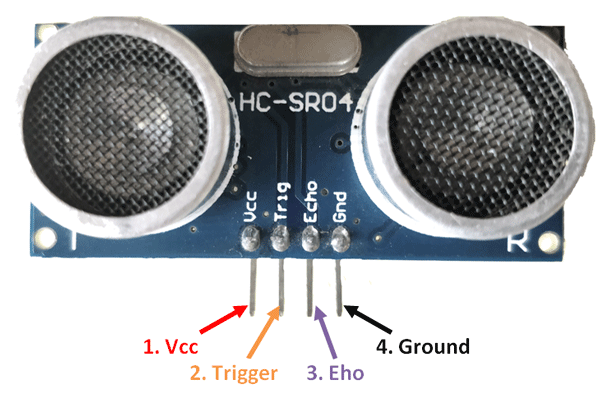
Ultrasonic Sensor Pinout
The HC-SR04 Ultrasonic Module has 4 pins, Ground, VCC, Trig, and Echo.
Connection
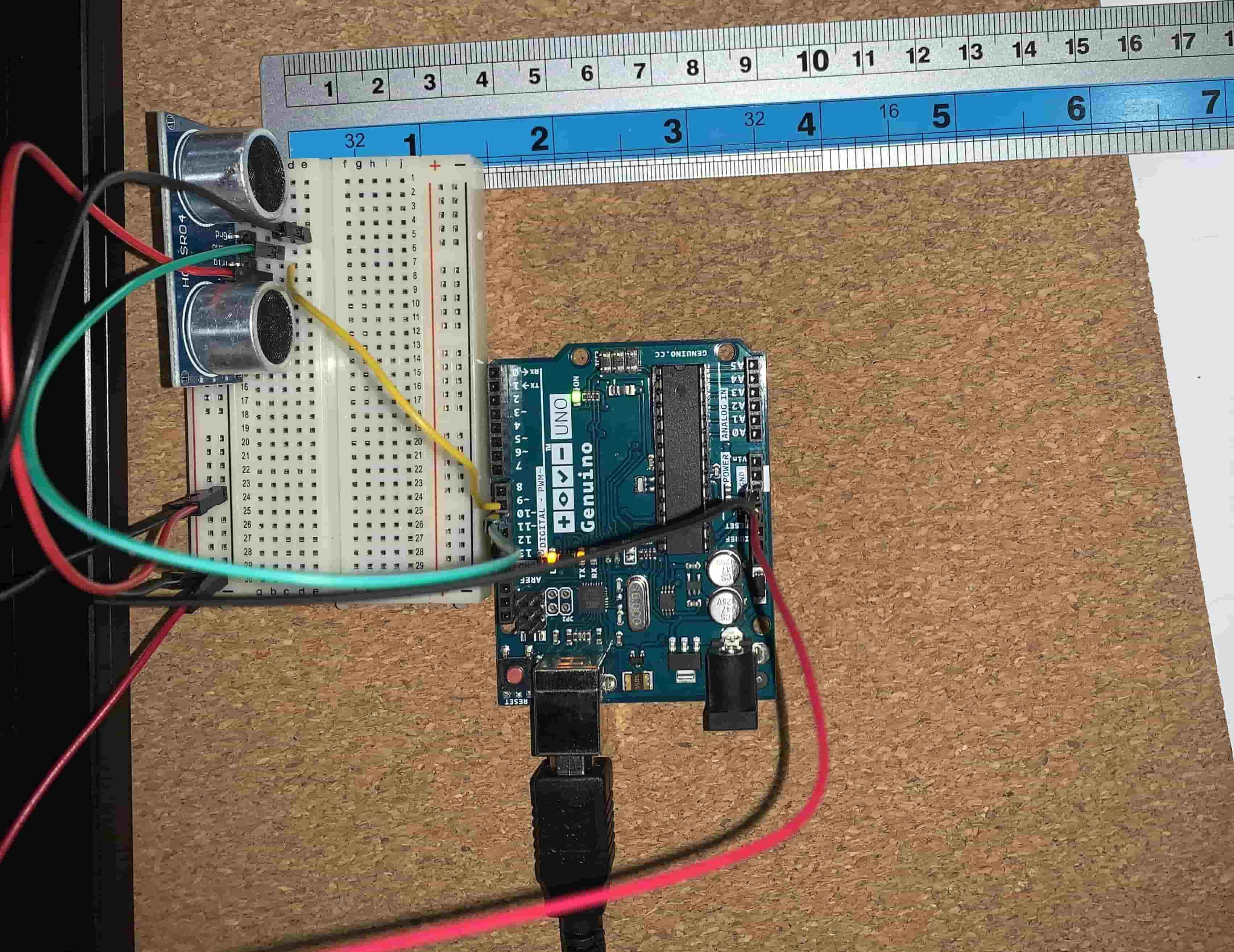
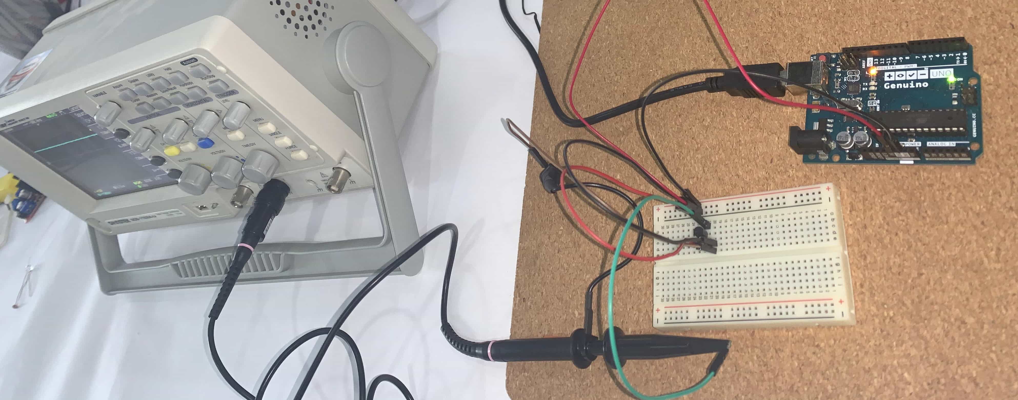
We connected the pin to the Arduino UNO like this connection shown in the picture and we connected the Ground and the Vout to the oscilloscope.
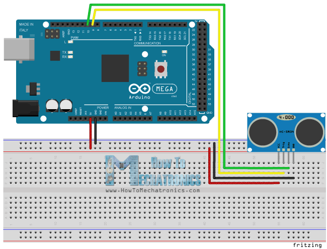
We put the ruler next to the sensor to put the object on the distance we want to measure.
Uploading the code:
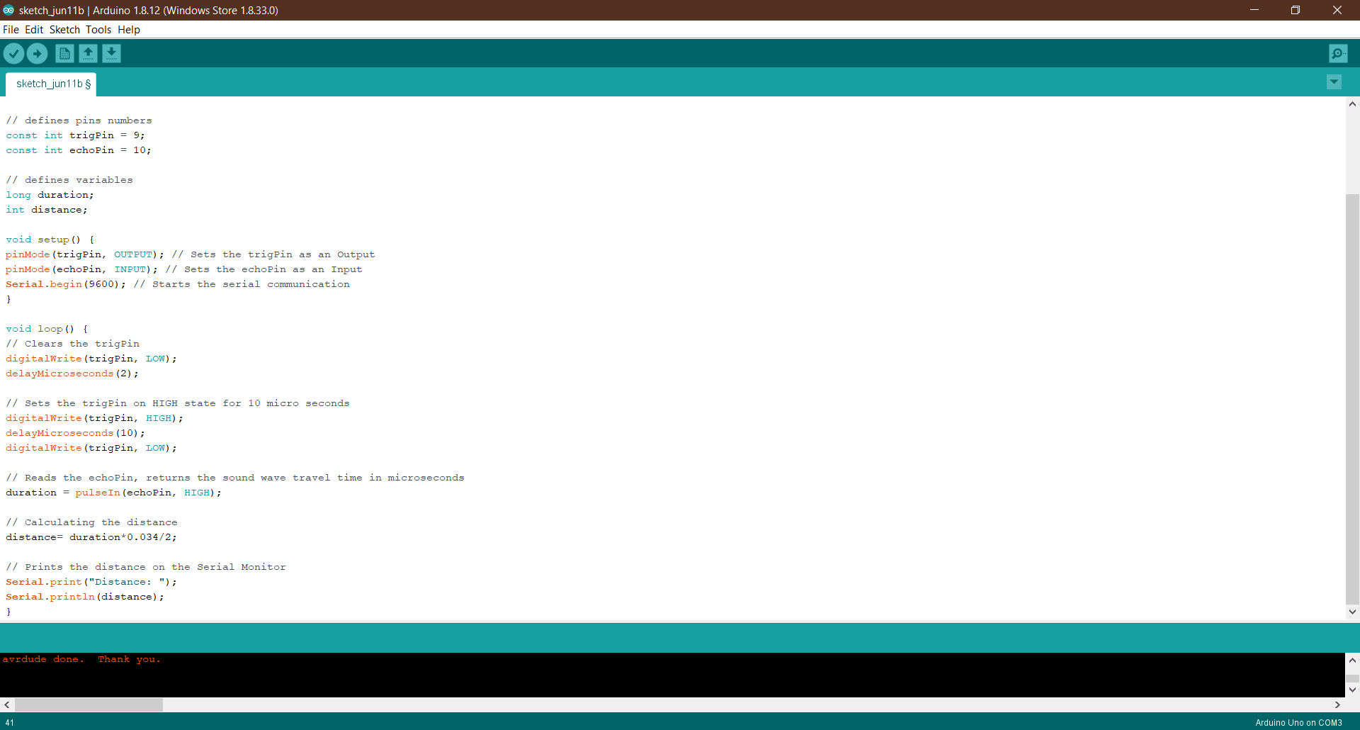
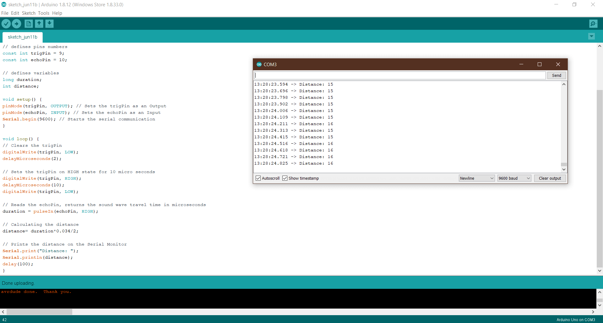
Source Code
/*
* Ultrasonic Sensor HC-SR04 and Arduino Tutorial
*
* by Dejan Nedelkovski,
* www.HowToMechatronics.com
*
*/

// defines pins numbers
const int trigPin = 9;
const int echoPin = 10;

// defines variables
long duration;
int distance;

void setup() {
pinMode(trigPin, OUTPUT); // Sets the trigPin as an Output
pinMode(echoPin, INPUT); // Sets the echoPin as an Input
Serial.begin(9600); // Starts the serial communication
}

void loop() {
// Clears the trigPin
digitalWrite(trigPin, LOW);
delayMicroseconds(2);

// Sets the trigPin on HIGH state for 10 micro seconds
digitalWrite(trigPin, HIGH);
delayMicroseconds(10);
digitalWrite(trigPin, LOW);

// Reads the echoPin, returns the sound wave travel time in microseconds
duration = pulseIn(echoPin, HIGH);

// Calculating the distance
distance= duration*0.034/2;

// Prints the distance on the Serial Monitor
Serial.print("Distance: ");
Serial.println(distance);
delay(100);
}
Reading the Wave
We connected the Echo and Trig pins of the sensor to two channels of the oscilloscope to measuring the time it takes the sound echo to return.
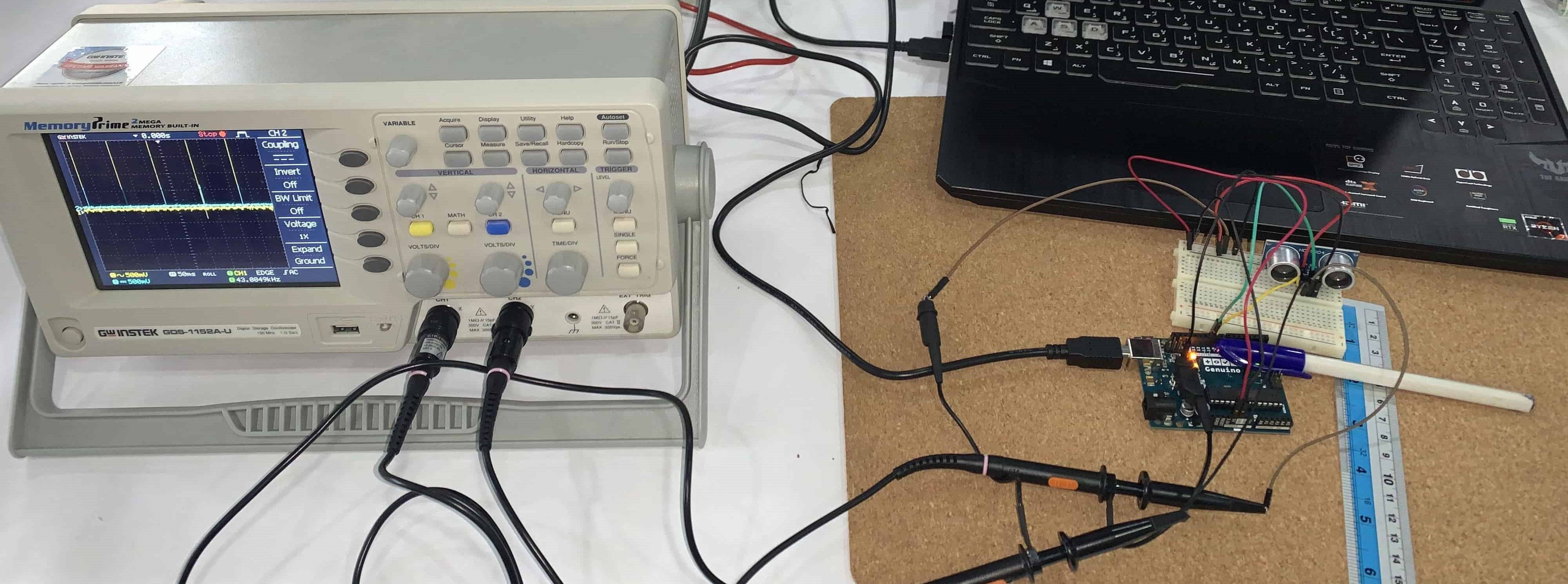
what time we get from the oscilloscope will be double because the sound wave needs to travel forward and bounce backward. So in order to get the distance in cm, we need to multiply the received travel time value from the echo pin by 0.034 and divide it by 2. This is the equation (the time in us):
Distance=time0.034/2*
First Read
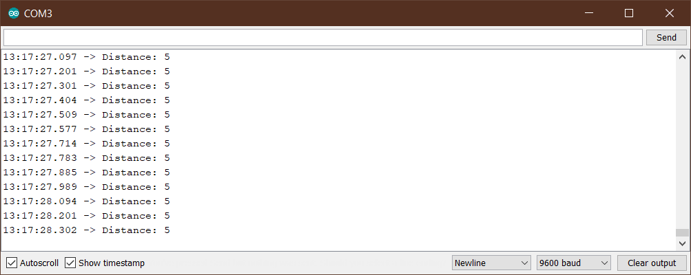
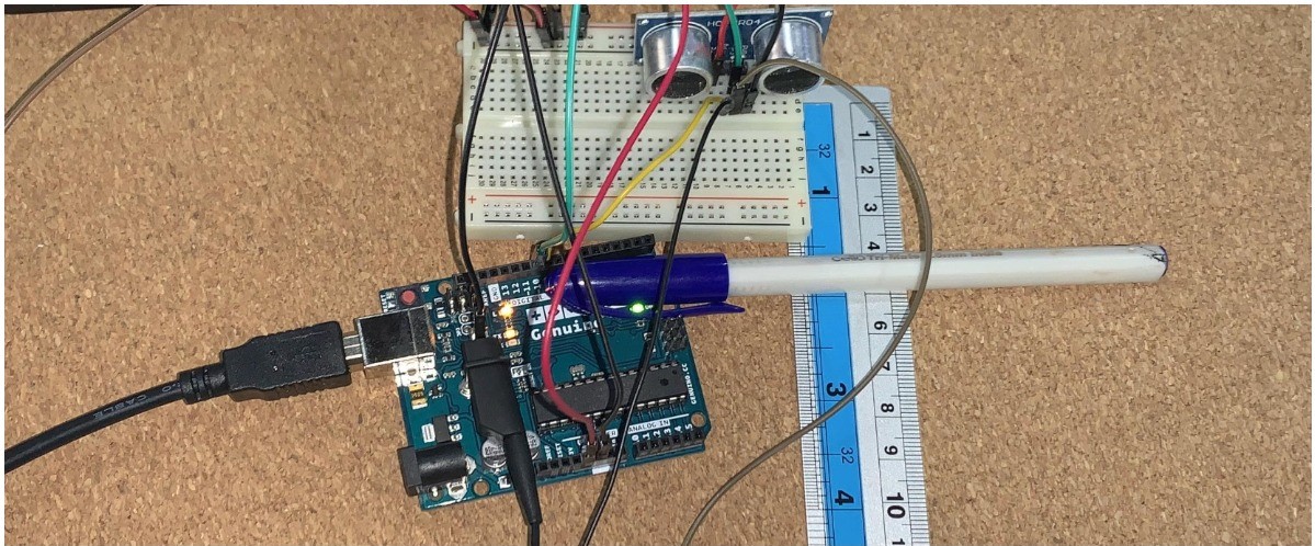 We put a pen about five centimeters from the sensor and that was read by Arduino Serial Monitor.
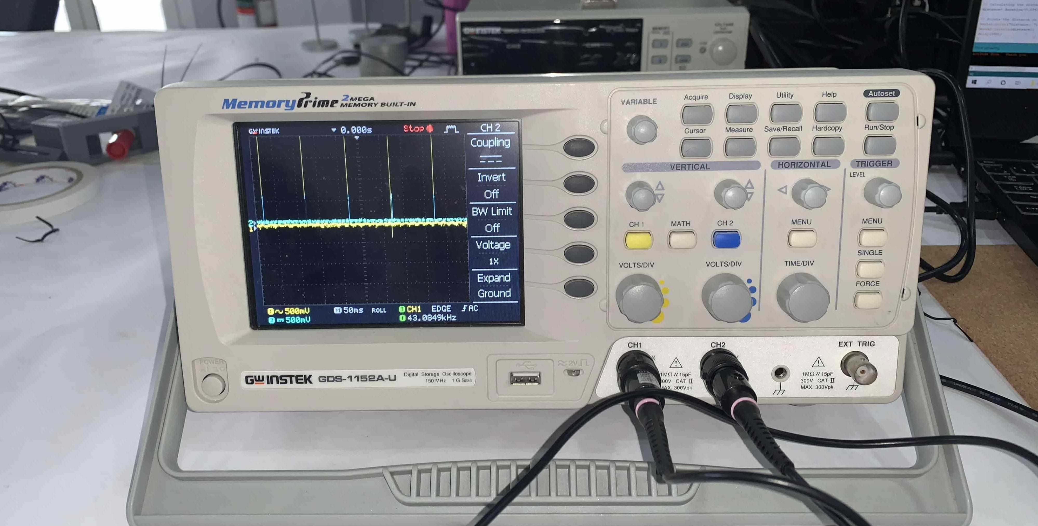
On the oscilloscope, we stopped the wave from moving to read the time period. The time was 440us and to find the distance we used this equation:
Distance=time0.034/2*
Distance=440 * 0.034/2= 7.48 cm
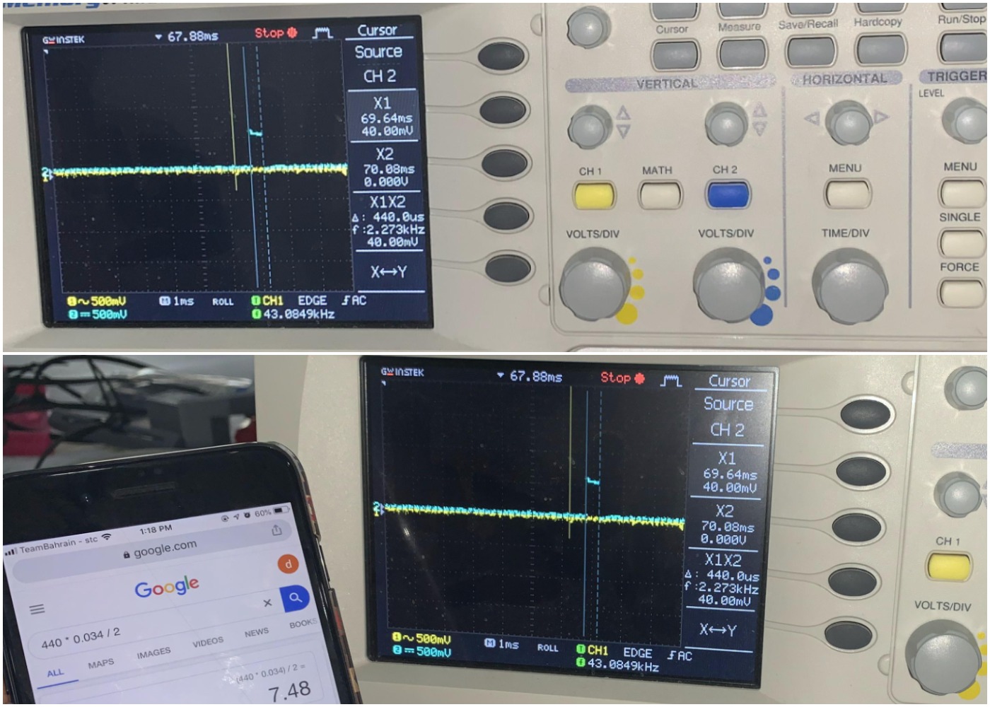
There is a difference between 7.48cm and 5cm, so we will read another distance.
Second Read
We put another material 15cm away from the sensor, and the reading on the Arduino Serial Monitor was between 15 and 16 cm.
Distance=time0.034/2
Distance=(1.041000)* 0.034/2= 17.68 cm
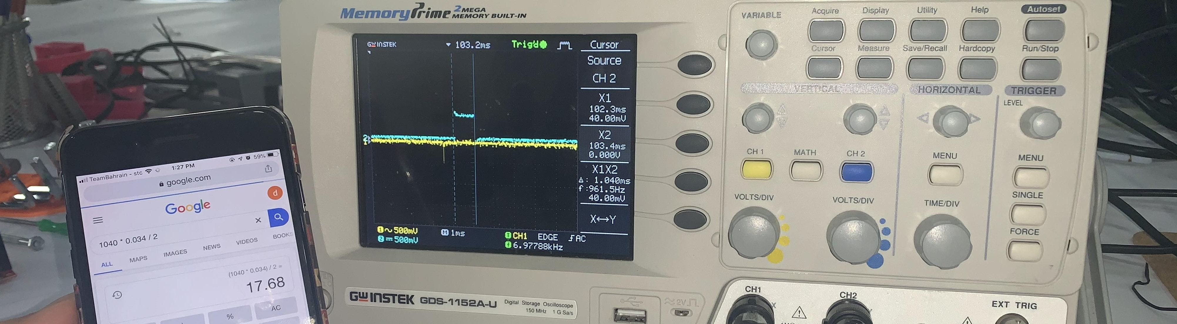 This distance is not far from 16cm. It seems that our locating of the wave on the oscilloscope is not accurate.
Useful Links
- Ultrasonic Sensor HC-SR04 and Arduino Tutorial
- HC-SR04 Datasheet and Pinout – Ultrasonic Sensor Noncontact Range Detection
- Ultrasonic Sensor FAQs
Monitoring analog Signal Using TMP36 Temperature Sensor
We measured the analog value of a temperature sensor using an oscilloscope. An oscilloscope is a type of electronic test instrument that graphically displays varying signal voltages, usually as a calibrated two-dimensional plot of one or more signals as a function of time.
Pin Definitions
TMP36 has just 3 pins, 2 for the power supply, and one for the analog output. The output pin provides a voltage output that is linearly proportional to the Celsius (Centigrade) temperature.

Connections
We connected the pin to the Arduino UNO, we connected the Ground and the Vout to the oscilloscope.
After that, we read the wave voltage. To convert millivolts into temperature, we use this equation:
Centigrade temperature = [(analog voltage in mV) - 500] / 10
First Read
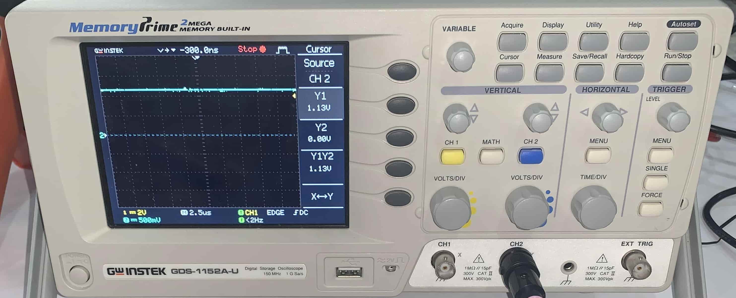
To convert 1.13V to Celsius temperature:
Centigrade temperature = [(1.13/1000) - 500] / 10
Centigrade temperature = -49.99 °C
That is not a reasonable value, we repeat the reading.
Second Read
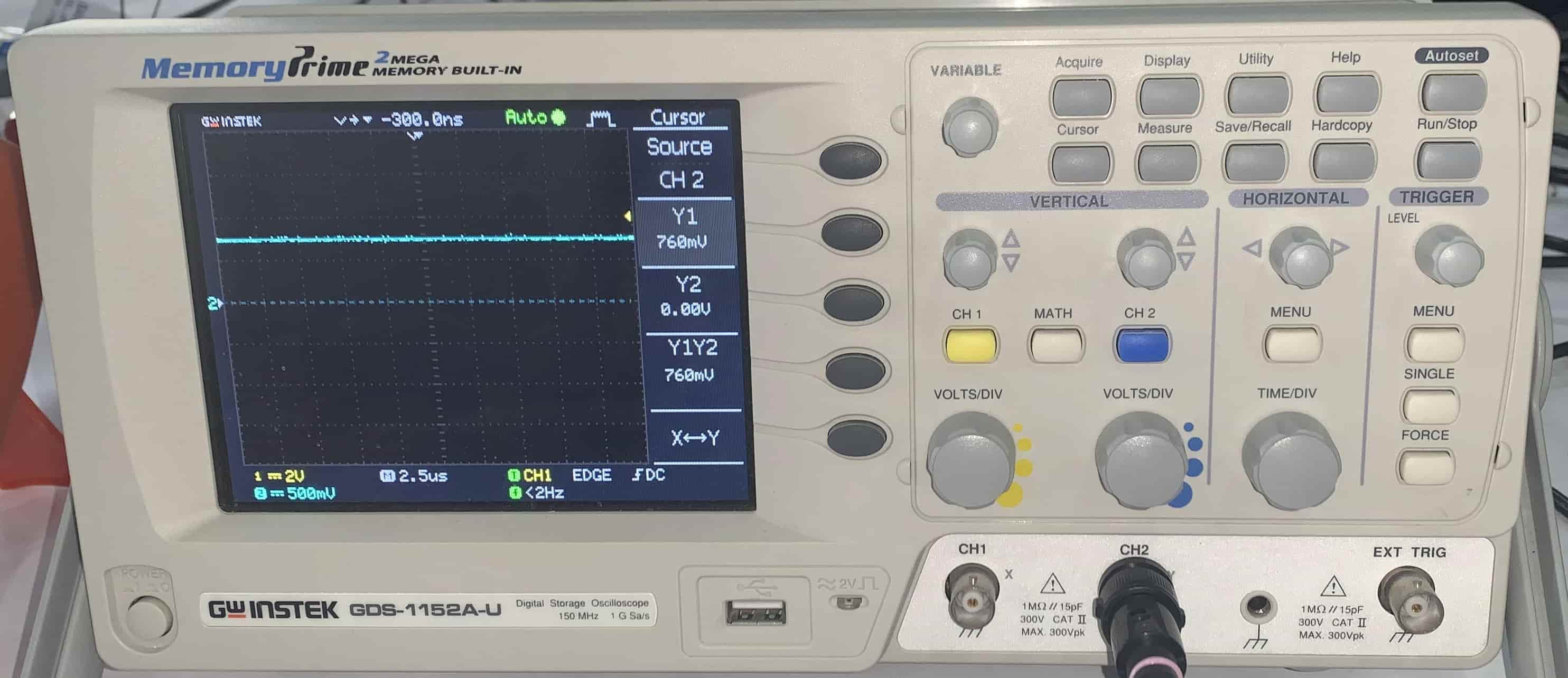 To convert 760mV to Celsius temperature:
Centigrade temperature = [(760) - 500] / 10
Centigrade temperature = 26 °C
That is a reasonable value, it shows the room temperature.