Electronics Design
Group Assignment For this week the group assignment is to Use the test equipment in your lab to observe the operation of a microcontroller circuit board (in minimum, check operating voltage on the board with multimeter or voltmeter and use oscilloscope to check noise of operating voltage and interpret a data signal)
multimeter

A multimeter or a multitester, also known as a VOM (volt-ohm-milliammeter), is an electronic measuring instrument that combines several measurement functions in one unit. A typical multimeter can measure voltage, current, and resistance. Analog multimeters use a microammeter with a moving pointer to display readings.
To check the operating voltage on the board an Arduino Mega is used and blinking code is uploaded to the board
void setup() {
  // initialize digital pin LED_BUILTIN as an output.
  pinMode(LED_BUILTIN, OUTPUT);
}

// the loop function runs over and over again forever
void loop() {
  digitalWrite(LED_BUILTIN, HIGH);   // turn the LED on (HIGH is the voltage level)
  delay(1000);                       // wait for a second
  digitalWrite(LED_BUILTIN, LOW);    // turn the LED off by making the voltage LOW
  delay(1000);                       // wait for a second
}
Once the code is uploaded we do the following steps:
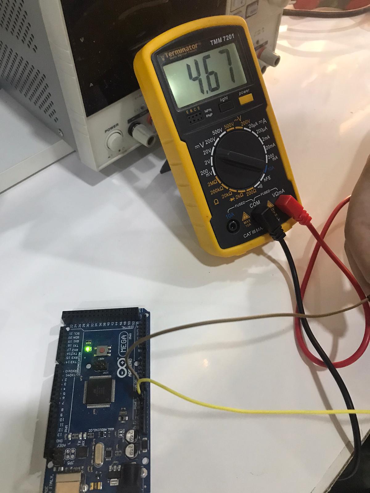
- Connect two jumper wire one to the ground and one to the vin pin and measure the result with the voltmeter we found it to be 4.67V
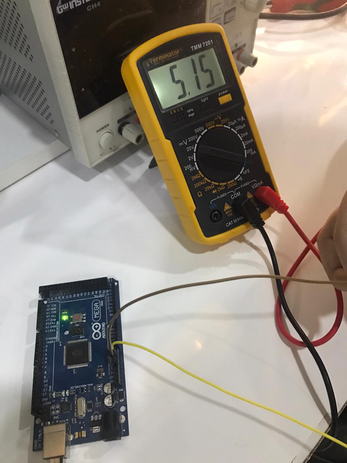
- We keep the GND wire as it is and connect the second wire with the 5v pin and again measure the voltage by the multimeter we found it to be 5.15v
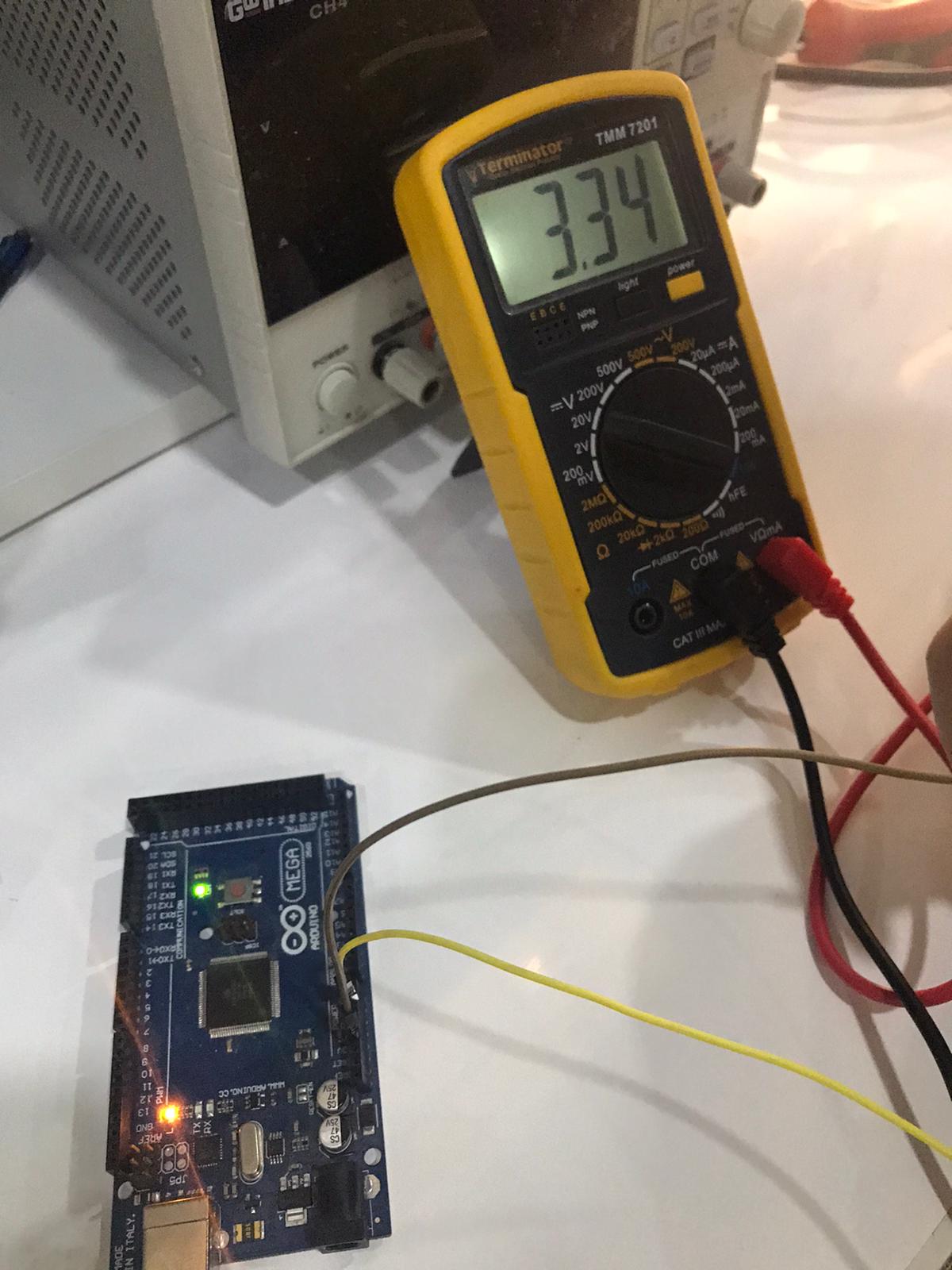
- Finally we again keep the GND wire and change the other wire to the 3.3v pin and we found the voltage to be 3.34v.
oscilloscope
An oscilloscope, previously called an oscillograph, and informally known as a scope or o-scope, CRO (for cathode-ray oscilloscope), or DSO (for the more modern digital storage oscilloscope), is a type of electronic test instrument that graphically displays varying signal voltages.
Blink
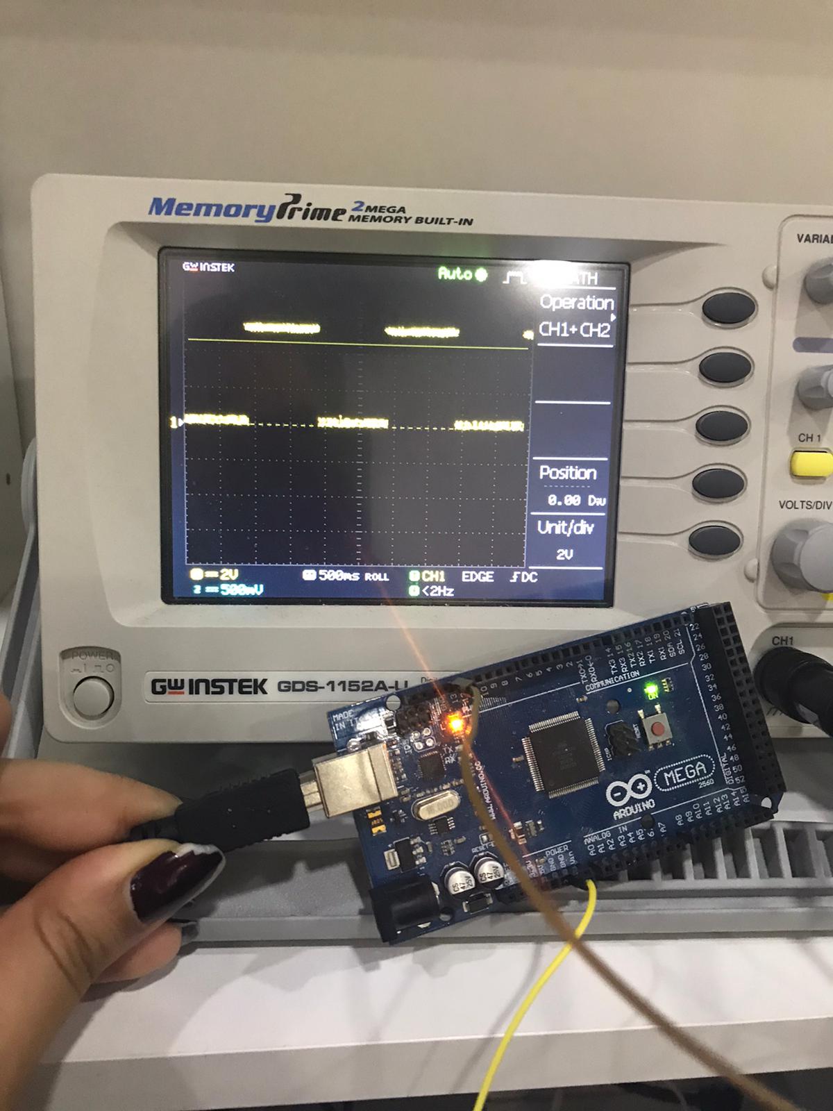
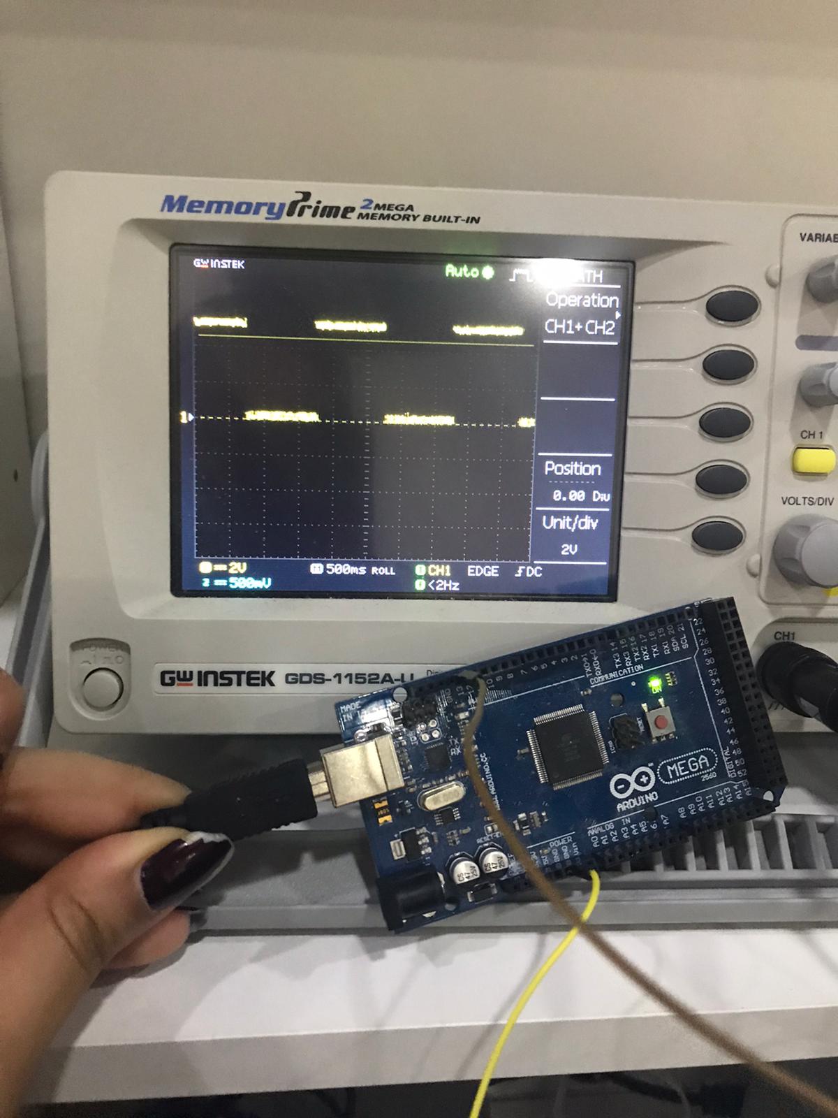
With the same blinking code and connect the oscilloscope prop to the pin 13 and the COM to the GND wire and we founf that the signal when the LED is on gives us 5v and 0V when it is off.
when the LED is on
when the LED is off
Fade
In order to see how the output signal is varying we upload a fading code as the follow
int led = 9;           // the PWM pin the LED is attached to
int brightness = 0;    // how bright the LED is
int fadeAmount = 5;    // how many points to fade the LED by

// the setup routine runs once when you press reset:
void setup() {
  // declare pin 9 to be an output:
  pinMode(led, OUTPUT);
}

// the loop routine runs over and over again forever:
void loop() {
  // set the brightness of pin 9:
  analogWrite(led, brightness);

  // change the brightness for next time through the loop:
  brightness = brightness + fadeAmount;

  // reverse the direction of the fading at the ends of the fade:
  if (brightness <= 0 || brightness >= 255) {
    fadeAmount = -fadeAmount;
  }
  // wait for 30 milliseconds to see the dimming effect
  delay(30);
}
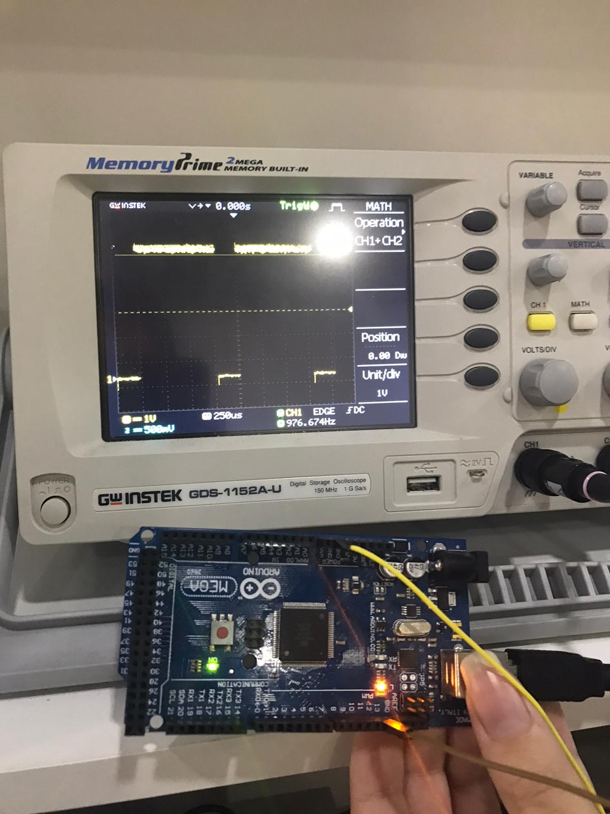
with the same connection in the blinking part we found that as the LED is fully bright the output signal is almost equal to 5v and as it fading we can notice the change in the waves as follow
when the LED is fully bright
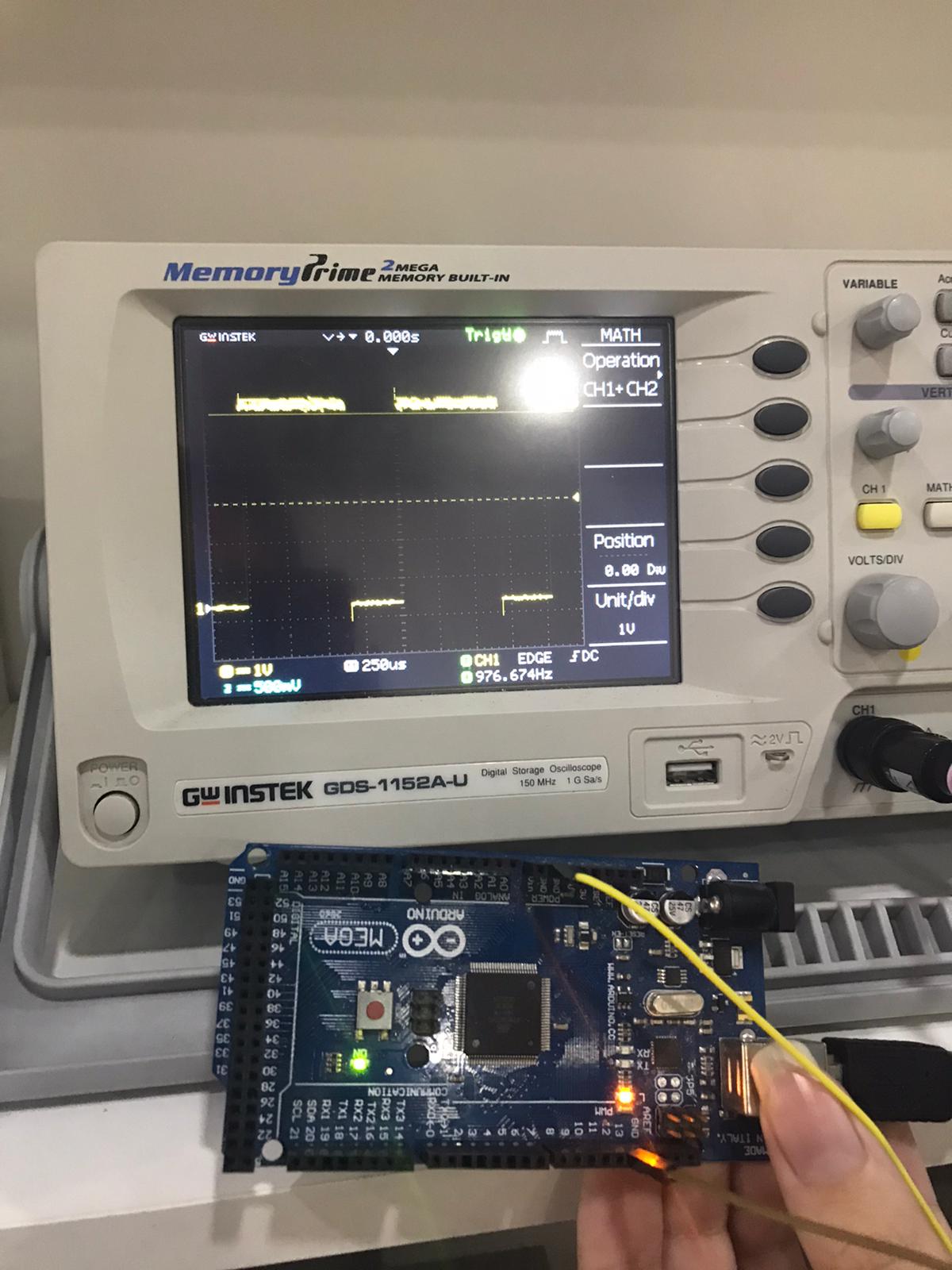
The wave when the led is less bright
The wave when the led is almost off
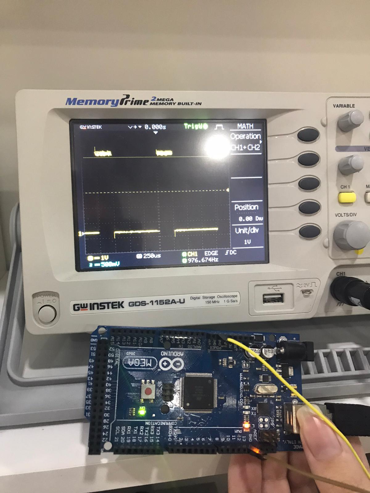
AS we can see the pulse duration is changing as the brightness of the LED change