Embedded Programming
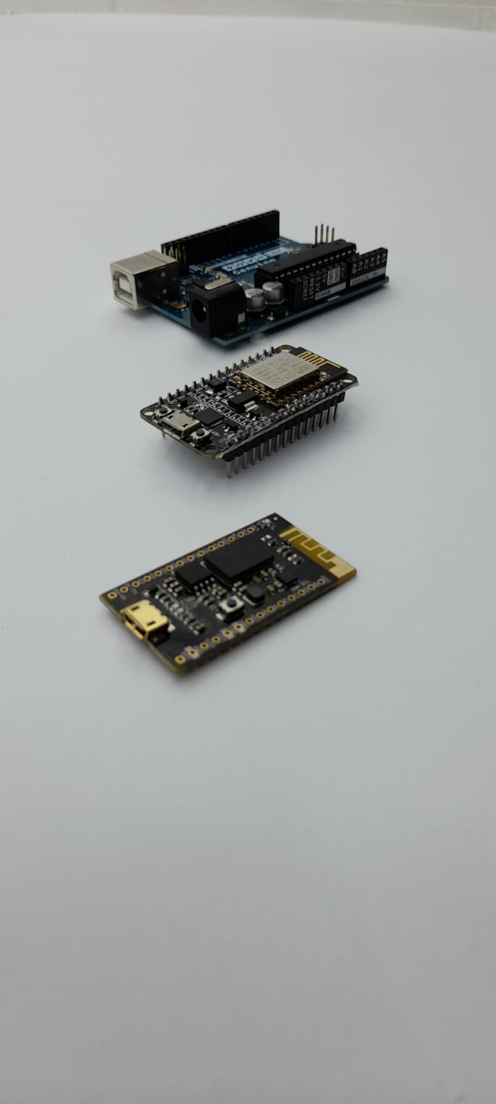
Group Assignment For this week the group assignment is Compare the performance and development workflows for different microcontroller families
AVR (ATmega328P)
The ATmega328 is a single-chip microcontroller created by Atmel in the megaAVR family (later became Microchip Technology acquired Atmel). It is based on a modified Harvard architecture 8-bit RISC processor core.
Specs
| Parametres | spec |
|---|---|
| Operating Voltage | 1.8 to 5.5 |
| Digital I/O pins | 32 |
| Flash Memory | 32 |
| Number of bits | 8-bits |
| ADC | 10-bit A/D converter, 8-channels |
| Max Speed | 16MHz |
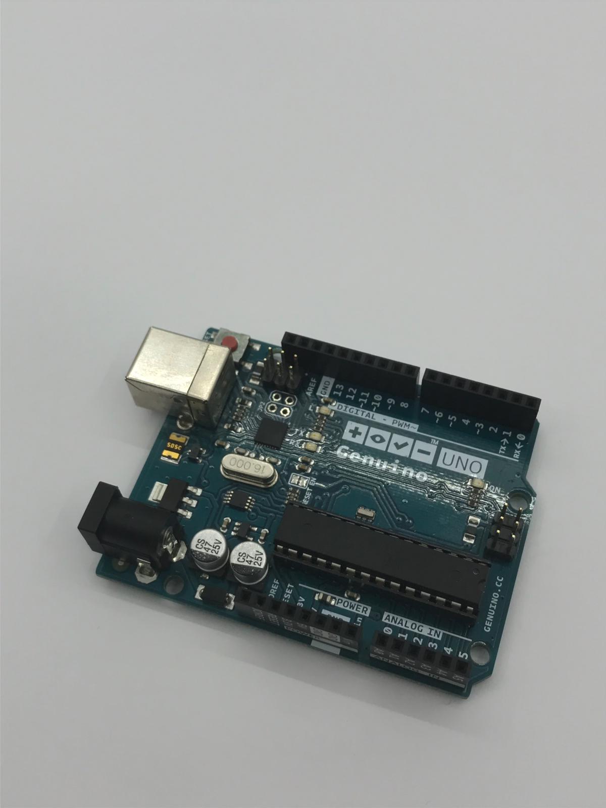
Microcontroller board
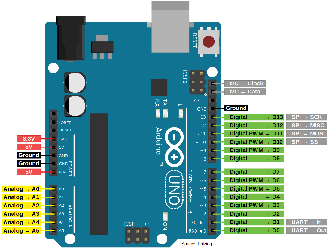
Microcontroller pinout
programming enviornment
Arduino IDE
code
Tested the Arduino with a Servo using an example code to sweep the servo between 0 and 180 degrees
/* Sweep
 by BARRAGAN <http://barraganstudio.com>
 This example code is in the public domain.

 modified 8 Nov 2013
 by Scott Fitzgerald
 http://www.arduino.cc/en/Tutorial/Sweep
*/

#include <Servo.h>

Servo myservo;  // create servo object to control a servo
// twelve servo objects can be created on most boards

int pos = 0;    // variable to store the servo position

void setup() {
  myservo.attach(9);  // attaches the servo on pin 9 to the servo object
}

void loop() {
  for (pos = 0; pos <= 180; pos += 1) { // goes from 0 degrees to 180 degrees
    // in steps of 1 degree
    myservo.write(pos);              // tell servo to go to position in variable 'pos'
    delay(15);                       // waits 15ms for the servo to reach the position
  }
  for (pos = 180; pos >= 0; pos -= 1) { // goes from 180 degrees to 0 degrees
    myservo.write(pos);              // tell servo to go to position in variable 'pos'
    delay(15);                       // waits 15ms for the servo to reach the position
  }
}
demo
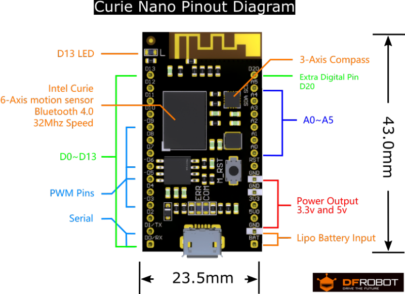
Intel Quark ( Intel Curie Module)
The Arduino 101 is a learning and development board which contains the Intel Curie Module, designed to integrate the core’s low power-consumption and high performance with the Arduino’s ease-of-use. The 101 adds Bluetooth Low Energy capabilities and has an on-board 6-axis accelerometer/gyroscope, providing exciting opportunities for building creative projects in the connected world. More information about the technical specifications and documentation can be found on the Arduino 101 product page.
(Above from Arduino main site)
The module contains two tiny cores, an x86 (Quark) and a 32-bit ARC architecture core, both clocked at 32MHz. The Intel toolchain compiles your Arduino sketches optimally across both cores to accomplish the most demanding tasks.
Specs
| Parametres | spec |
|---|---|
| Operating Voltage | 3.3V (5V tolerant I/O) |
| Digital I/O pins | 14 (of which 4 provide PWM output) |
| Flash Memory | 196 kB |
| Number of bits | 32bits |
| ADC | 19 channels 12 bits |
| Max Speed | 32MHz |
Microcontroller board
Microcontroller pinout
programming enviornment
Arduino IDE
code
Tested a simple blink code on built in LED
/*
  Blink

  Turns an LED on for one second, then off for one second, repeatedly.

  Most Arduinos have an on-board LED you can control. On the UNO, MEGA and ZERO
  it is attached to digital pin 13, on MKR1000 on pin 6. LED_BUILTIN is set to
  the correct LED pin independent of which board is used.
  If you want to know what pin the on-board LED is connected to on your Arduino
  model, check the Technical Specs of your board at:
  https://www.arduino.cc/en/Main/Products

  modified 8 May 2014
  by Scott Fitzgerald
  modified 2 Sep 2016
  by Arturo Guadalupi
  modified 8 Sep 2016
  by Colby Newman

  This example code is in the public domain.

  http://www.arduino.cc/en/Tutorial/Blink
*/

// the setup function runs once when you press reset or power the board
void setup() {
  // initialize digital pin LED_BUILTIN as an output.
  pinMode(LED_BUILTIN, OUTPUT);
}

// the loop function runs over and over again forever
void loop() {
  digitalWrite(LED_BUILTIN, HIGH);   // turn the LED on (HIGH is the voltage level)
  delay(1000);                       // wait for a second
  digitalWrite(LED_BUILTIN, LOW);    // turn the LED off by making the voltage LOW
  delay(1000);                       // wait for a second
}
demo
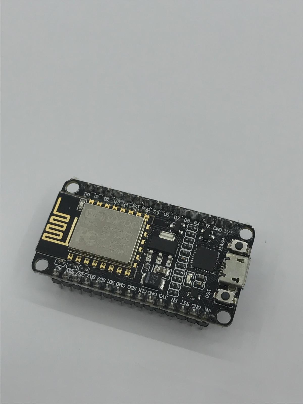
esp8266
The NodeMCU ESP8266 development board comes with the ESP-12E module containing ESP8266 chip having Tensilica Xtensa 32-bit LX106 RISC microprocessor. This microprocessor supports RTOS and operates at 80MHz to 160 MHz adjustable clock frequency. NodeMCU has 128 KB RAM and 4MB of Flash memory to store data and programs. Its high processing power with in-built Wi-Fi / Bluetooth and Deep Sleep Operating features make it ideal for IoT projects. (source https://components101.com/development-boards/nodemcu-esp8266-pinout-features-and-datasheet )
Specs
Microcontroller: Tensilica 32-bit RISC CPU Xtensa LX106
| Parametres | spec |
|---|---|
| Operating Voltage | 3.3V |
| Digital I/O pins | 16 |
| Flash Memory | 4MB |
| Number of bits | 32-bit |
| ADC | 10-bit resolution |
| Max Speed | 80 MHz |
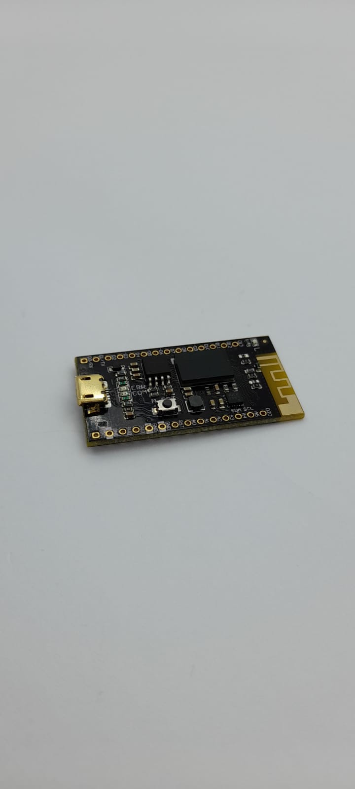
Microcontroller board
Microcontroller pinout
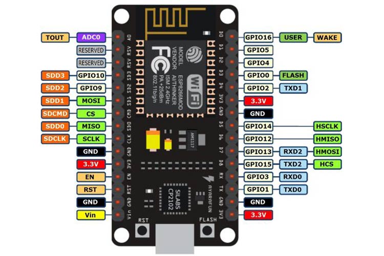
programming enviornment
Arduino IDE We first had to add the link to ESP library in the setting for Additional Board manager

Then searched for the board in board manager and added it

code
We started by testing an existing code from the sample sketches and we then started modifying it.
/*
  ESP8266 Blink by Simon Peter
  Blink the blue LED on the ESP-01 module
  This example code is in the public domain

  The blue LED on the ESP-01 module is connected to GPIO1
  (which is also the TXD pin; so we cannot use Serial.print() at the same time)

  Note that this sketch uses LED_BUILTIN to find the pin with the internal LED
*/

void setup() {
  pinMode(LED_BUILTIN, OUTPUT);     // Initialize the LED_BUILTIN pin as an output
}

// the loop function runs over and over again forever
void loop() {
  digitalWrite(LED_BUILTIN, LOW);   // Turn the LED on (Note that LOW is the voltage level
  // but actually the LED is on; this is because
  // it is active low on the ESP-01)
  delay(1000);                      // Wait for a second
  digitalWrite(LED_BUILTIN, HIGH);  // Turn the LED off by making the voltage HIGH
  delay(2000);                      // Wait for two seconds (to demonstrate the active low LED)
}
Then we changed the pin and duration of the delay to pin 16 which also addressed to an on Board LED.
void setup() {
  pinMode(16, OUTPUT);

// the loop function runs over and over again forever
void loop() {
  digitalWrite(16, LOW);
  delay(500);
  digitalWrite(16, HIGH);
  delay(500);
}